Latest update: Dec 26, 2014
How to Disassemble and Modify the Heating Oil Burner.
Modifying the burner consists of disassembly of the burner as well as adding several new parts. It is recommended to read this entire document before actually starting the process of the modification.
First disconnect the oil furnace from any external 120VAC power. The burner needs to be removed from the heating furnace. Since heating furnaces have different ways of running and connecting wires, tubing, etc. a typical burner unit will be shown and instruction given about things to watch out for. Be sure to label all wires, tubing, etc. that are disconnected as they will be reconnected later.
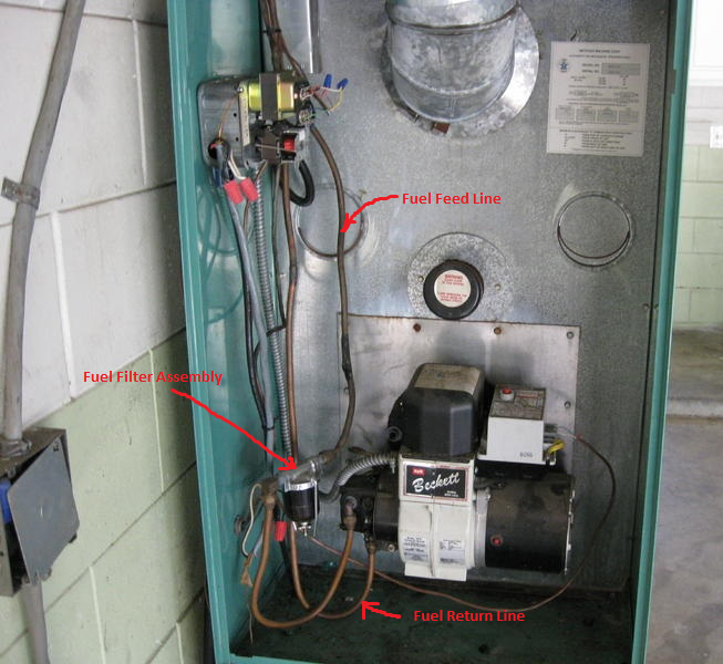
WARNING: fuel lines contain fuel when not running or in use so the fuel needs to be shutoff and fuel purged from the lines BEFORE they are disconnected at the burner oil pump or there may be a huge fuel mess. First locate the feed line and whether there is a return line. You need to know where/how they connect to the fuel tank and fuel filter and burner. Before fuel goes into the burner's oil pump it passes through a fuel filter that removes very small particles to keep the nozzle from clogging. This is the fuel feed line. In normal operation the burner oil pump sucks fuel to the pump through this line. Normally there is a fuel shutoff safety valve on the input side of the filter and this needs to be shut off so that fuel will not be able to come through this path. There may also be a fuel return line. DO NOT remove any copper lines yet. Now comes a sometimes tricky part - the fuel return line. This line should also have a valve. Normally this is a check valve located near the tank. "Why" you may ask, "if its just the return line"? Here's the problem. Let's assume (like in the picture further below) there is no return check valve. Let's also assume there is a fair amount of fuel in the tank. Now let's also assume the copper line in this picture goes up from the burner, through a wall and then outside and directly into the bottom (or near the bottom) of an outdoor tank such that the return is below the fuel level. This is a common scenario. The scenario is basically one where the burner oil pump is lower than the fuel level in the tank with fuel in the return line. If this is the case, then if the return line was disconnected without a shutoff or check valve, fuel will siphon out of the tank and all over the floor until the fuel level in the tank is lower than where the disconnect occured and that may mean the entire tank drains out! I almost had this problem once until I realized it and quickly put the squirting return line back on and tightened it back up. Anyway, have an old bucket handy and some rags for when doing the disconnect as there will be some fuel that will drain out of the lines. If there is not a shutoff or check valve on the return line then life is not going to be to easy since this line will need to be cleared to keep a siphon from happening and ruining your day.
***
This paragraph is for those who do not have a shutoff valve on the return line. One method is find the feed line where it enters near the bottom of the tank and physically raise the external copper tubing above the level of the tank (at minimum above the fuel level) and physically cut the line and install a check valve. This assumes there is extra copper tubing coiled up that would allow you to do this. This is what I had to do with my tank as it didnt have a shutoff or check valve. This is not that difficult but a tube cutter will be needed and a tube flaring kit so you can make flares on the ends of the copper tubing that gets cut. This will allow you to install tube flarings fitings and a valve. Use tube flaring fittings, not compression fittings, as this is the standard method for oil burner systems. When the tubing is raised above the tank and cut, be ready to catch a small amount of oil. Also drain out what you can from the return line thats coming from the furnace and BE SURE to keep the copper tube that goes to the fuel tank as high as possible (at least above the fuel level in the tank) so the tank doesn't start draining out. If there is no extra copper tubing that can be raised, so you can cut, and install a valve, then this part of the conversion has just become more difficult. Most likely the tank will first need to be completely drained. I recommend getting a large 275 gallon (or larger) poly tank. I typically buy them on Craigslist for $40 - $75 in good used condition. You may want a couple of these tanks anyway for getting waste oil. Empty, they weigh about 120lbs and I can roll and tip them up onto the tailgate of my truck, go transfer waste oil into it, then bring it home to transfer into another poly tank, and then easily remove the tank from my truck. Anyway, once the tank is drained, disconnect the return line at the burner's oil pump. Be ready with a 5 gallon bucket or two to catch all the remaining oil that may still be in the tank and line. Once this line is drained, I recommend installing the return line check valve close to the fuel tank.
***
Now with the fuel feed shutoff valve turned off and either a working check valve or shutoff on the return line, disconnect the line between the fuel filter and the oil burner's fuel pump. There will be some fuel in this line so it is recommended that some old rags be put just below the line and then carefully loosening the copper line connections while draining the oil into an old bucket. Anyway, think about how to best do it for your particular setup before disconnecting it, as it can be messy. You may also want to have something to plug the oil pump hole you just opened as it may leak due to the return line still has fuel in it and may backfeed through the pump. Now disconnect the line between the oil pump and the return line valve.
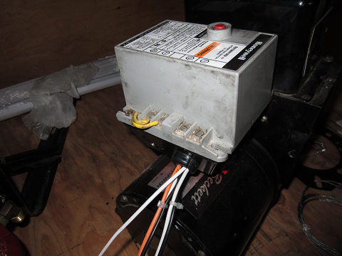
The burner uses 120VAC power to run the motor and high voltage transformer/igniter, etc.. Sometimes you will see a flexible metal conduit containing these wires going into the side of the burner unit as seen below. Sometimes they may go directly into the metal electrical box under the Primary Control Unit. In either case, disconnect the wires outside of the burner and label them. If there is a metal conduit then you will need to disconnect the conduit by opening the metal junction box that it's connected to, unscrewing the conduit locknut, and disconnecting the wires inside the junction box. Please label and note where they will need to be reconnected.
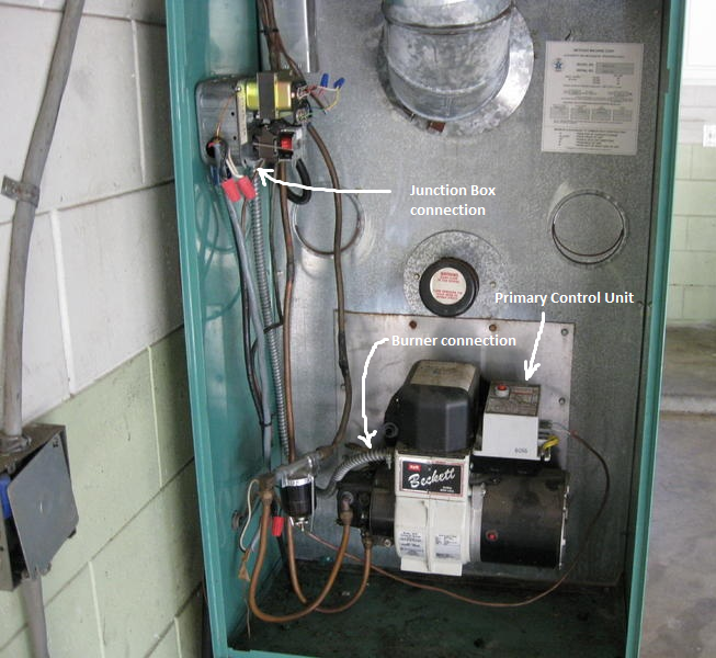
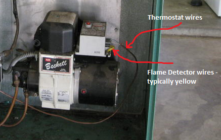
Notice the side connections on the Primary Control Unit. The two T-T terminals are for the thermostat wires and the other two F-F terminals are typically the flame detector wires (yellow). Label the T-T and F-F wires and disconnect them from the Primary Control Unit.
At this point, all wires and tubes should be disconnected from the burner unit. Double check to be sure. The burner mounts to the heating unit via a flange and normally 3 nuts. The nuts must be loosened but do not have to be removed. Notice the flange they are tightened to. The flange is made so that once the nuts are loosened, the entire burner unit may be rotated counterclockwise a few degrees and then pulled straight out. Remember, there is a flame tube going inside to the combustion chamber so try to keep the flange parallel to the wall its being removed from to make removal easier. Note. There is still a little bit of fuel inside the oil pump and it may spill out during removal of the burner from the furnace, so you may want to either have rags handy or plug the oil pump holes.
Set the burner on a bench with room to disassemble it.
Now remove the Primary Control Unit from the burner by removing some screws at its corners and lifting it up just a little as there will be wires attached between the Primary Control Unit and the metal box it was attached to. You don't want to accidentally break or disconnect anything while lifting it up. In the picture below, notice the 3 wires - orange, black and white. The black & white wires are the 120VAC power input to the unit. The black is known as the "hot" and the white is usually tied to ground or nuetral. These power inputs supply power to the circuit & timers inside. The orange wire is the power output. Together, the orange and white wires form a pair that are used to supply power to the burners motor and high voltage transfomer when the burner is in normal running operation. Should the controller decide theres's a problem or fault, then no power will be supplied to the orange wire.
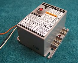
Picture of a new Honeywell Primary Control Unit.
Remember the black and white power wires you just disconnected? Trace these wires and note where they connect inside the burner unit. This is typically under the Primary Control Unit. Both of these wires will be connected to other wires using "wire nuts". Later, when we connect the PID controllers, etc. we will need to tap into these wire nuts to get power. They can be removed (not right now) by screwing them off in a counterclockwise motion. Wires come in different size "guages". These black and white wires are typically 14 guage multi stranded copper wire. Wire nuts have a limit to how many wires they can hold, so as we add wires, we may go past the limit and need a larger wire nut or break the wires into a couple groups and connect a single wire between the groups. If you're not familiar with wire nuts, go to a hardware store or a store like Home Depot and in the electrical dept. look for wire nuts. On the package it will tell you how many wires and of what guage that particular wire nut can handle.
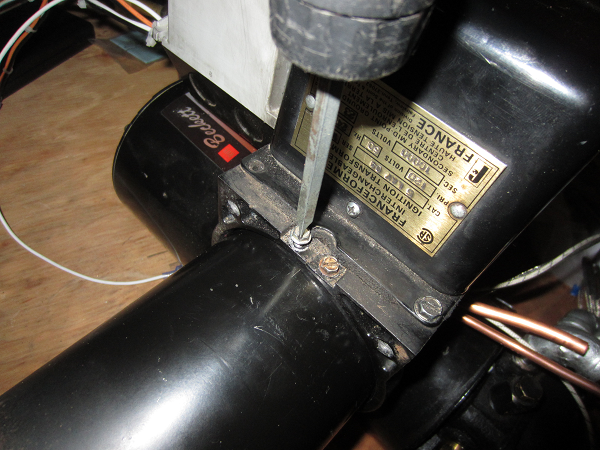
Now lets start disassembling the burner. First locate the 4 Mounting Flange bolts.
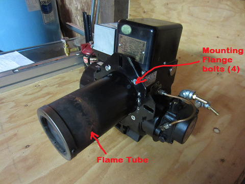
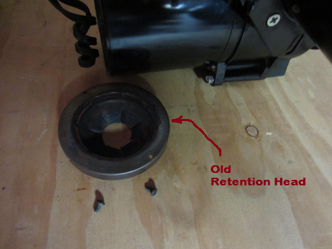
Also note where the 2 Retention Head screws are located. There is typically one on each side.
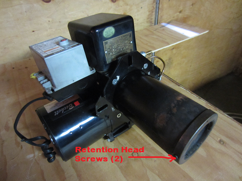
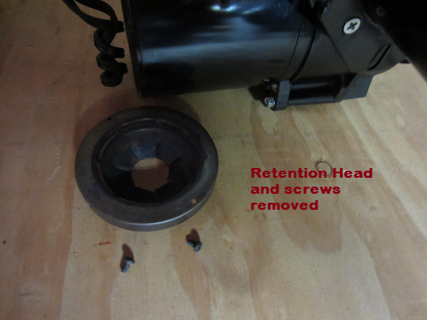
First remove the 2 retention head screws and slide off the retention head. This retention head will not be used. You will be making a new one of a different style that will be needed to burn the various waste oils.
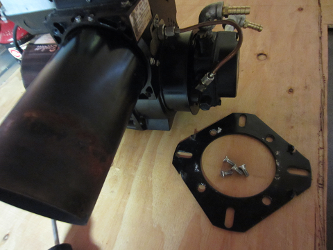
Now remove the Mounting Flange bolts and slide off the flange. Don't forget how it goes back on.
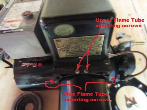
Now remove the 4 inch round metal flame tube. This tube is typically held on with 4 sheet metal type screws where the tube connects to the main burner body. The screws are typically located as follows: 2 at top center of the tube, one 90 degrees counterclockwise from top/center, and the other 90 degress clockwise from top/center as shown in the following picture.
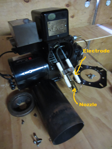
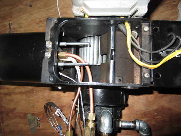
Now you can begin to see some of the internal parts of the burner including the nozzle and two electrodes (white cylindrical objects). Notice the electrode wire tips are very close to the output of the nozzle. This is because when the burner is running, and arc is constantly between the two electrode tips which causes the fuel to ignite as it atomizes on its way out of the nozzle. This typically creates a 10-12 inch flame beyond the retention head which heats the firebox in the furnace.
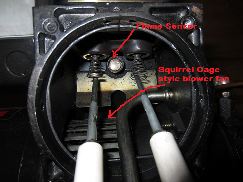
In this next picture you can see the Flame Sensor (CAD cell type) and part of the squirrel cage style blower fan. Also notice the end of the electrodes under the igniter and how the igniter connects to them with springs when the igniter is in its normal operating position.
The igniter is basically a large transformer to create a high voltage arc. Next remove the two scews keeping the igniter held down. The screws are on the flame tube side of the igniter. On the opposite side of the igniter, there's a hinge so that when the screws are removed, the igniter can be flipped open as shown below. Now notice the internal components. The two electrodes will be reused but the nozzle and associated feed tubes, etc. will no longer be needed as they will be replaced by a new machined aluminum block used to heat the new siphon feed style nozzle, as well as new oil and air supply lines that connect to it.

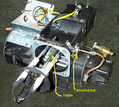
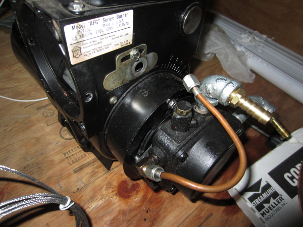
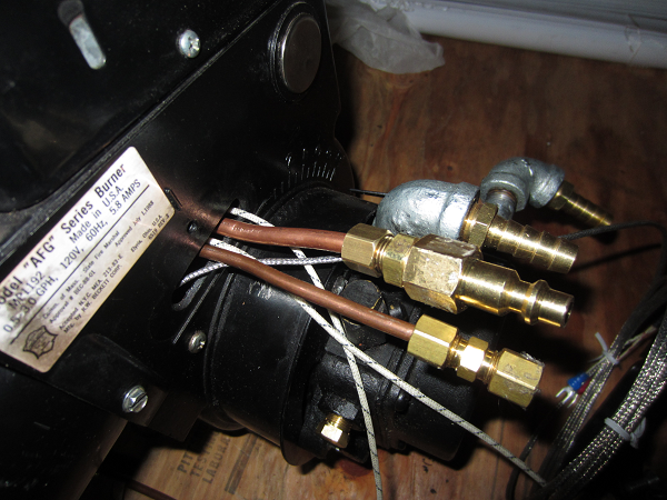
To remove this assembly, notice that the oil feed tube (we'll call it a J tube) makes a 90 degree bend and goes out the side of the body where it is held in place with a knurled nut. First remove the thin copper tube that connects to the oil pump and the end of the J tube at the knurled nut. This is the high pressure feed I told you about from the oil pump to the nozzle. The output connection at the oil pump will no longer be used and will need to be plugged with a brass plug. Also notice the two yellow wires from the CAD cell shown below and how they go to the Primary Control Unit.
Now remove the knurled nut, as well as the thin metal plate under it, and then carefully remove the nozzle assembly. Do not drop the electrodes as the white ceramic insulators may break and they are expensive to replace.

One other thing I'd like to mention is the brass shutoff valve in the above pictures. This is known as a "fusible link oil safety valve". These valves have a lead or other soft metal core that melts and closes the valve so that the system won't keep feeding oil to the heating equipment if the area is on fire. These are standard oil safety valves used at the oil burner on the feed line. Check the brand to see that the valve can be installed in any position - (vertical, horizontal, upside down). Normally they can because they have a spring loaded valve, but be sure to check. In a fire a lead core melts at 165 F and a spring in the valve assembly snaps the valve shut to assure that the heating system does not feed oil to a building fire. If you have a furnace that has a return line that feeds into a tank below the level of the fuel and the burner is below that level too, then a check valve, NOT a fusible link oil safety valve, would also be needed so that fuel is not siphoned back out of the tank through the return line and into the burning room should the return line break. The check valve must be installed in the proper oil flow direction. WARNING: Do NOT install an automatic oil line shutoff on the return oil line between the oil burner and the oil tank.
Now we are ready to setup and install the new Aluminum Nozzle Block and associated components. Before doing this look inside the body where the flame tube was attached and above the blower and you should see the CAD cell. Its round and maybe the size of a dime or nickel and typically has two yellow wires connected to it. These two wires are normally connected to two terminals on the Primary Control Unit. The CAD cell has a thin piece of glass that covers the actual sensor and it may be a good idea to gently clean it with a Q-tip and some rubbing alcohol as it needs to be clean to detect the flame.
1. The Heated Aluminum Nozzle Block
This is a custom made part that I machined. This block has many machined holes, some interconnecting internally, as well as threaded ports for connections. There is another person that sells a similar nozzle block called C K Burners (http://www.ckburners.com). If you would like details of how to machine this block, please contact me (click on the HDL Express logo above to get back to the main homepage where contact information is available).
SolidWorks Engineering Drawings
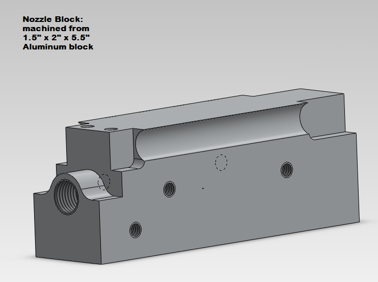
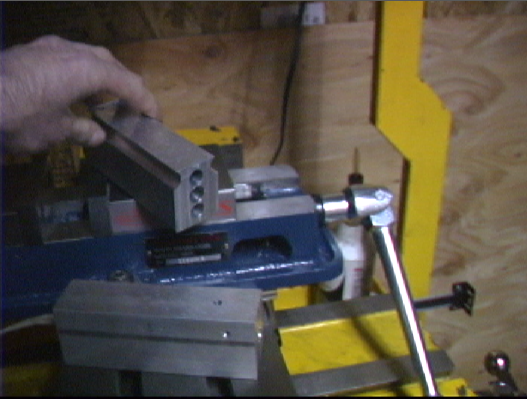
And here are some pictures of the actual aluminum nozzle blocks being made.
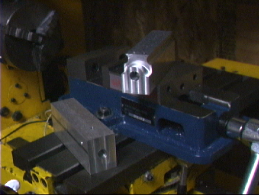
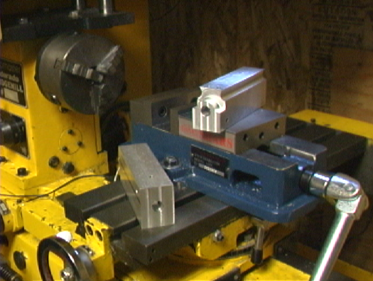
The block is 1.5 inch wide, 2 inches tall and 5.5 inches long. The Nozzle Block is used to heat both the waste oil and the incoming compressed air so that the waste fuel will ignite and burn properly. In this design the Nozzle Block is kept at a temperature of 300 F. This high of a temperature is needed due to waste motor oil properties. If just waste vegetable oil is burned, a lower temperature can be used.
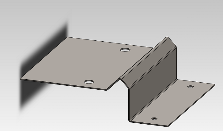
2. Creating the Mounting brackets/electrode clamps
The mounting brackets are made from 2 pieces of 3.25" by 4.8" sheet aluminum. Lines are marked, as measured from the short edge, at intervals of 2.2", 2.7", 3.05", and 3.8". The marks are the same on both aluminum pieces and also marked on the back side since some of the folds will be done from opposite sides when folding.
Drawing of bracket and the folds. All bends are either 90 degrees or 45 degrees.
Mounting holes are spaced 2.5" apart matching the nozzle block machined holes as well as two holes 2.5" apart for #8-1/2" screws with nuts. After you make and bend the part, place an electrode on the nozzle block, then lay the part on the block and electrode and mark the distance (looking at drawing above this would be from the left edge) to the block's mounting holes. Then center and drill the holes 2.5" apart. This is the easiest way in case your bends are a bit off.
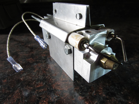
3. Assembling the Nozzle Block
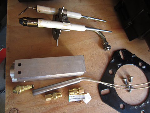
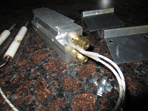
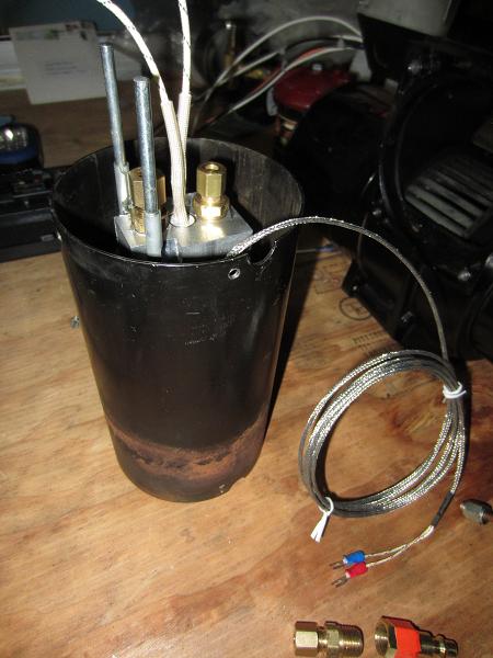
The Nozzle Block is heated using a 4 inch long, 1/2 inch diameter, 750 Watt Cartridge heater which goes inside the rear middle hole. The cartridge heater is controlled (turned on/off) by a PID controller in conjunction with a 25amp Solid State Relay. Shown below is the old nozzle assembly and the new nozzle block, cartridge heater and fittings.
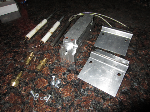
Here are all of the parts used for the new nozzle block assembly. On the top left are the original electrodes.
Now install the oil feed brass adapter. Later a length of 3/16" OD copper tubing is attached to this adapter. The length will depend on where you place the preheat/constant level tank in your particular application. The adapter fitting is 3/16" OD compression fitting on one side and 1/4" NPT on the other. The 1/4" NPT fitting is screwed into the lower Nozzle Block hole. A 3/16 copper tubing line was chosen so as to keep the oil from the Constant Level/Preheat Tank flowing at a fast enough rate so it doesn't cool too much before reaching the nozzle block. The larger the tube, the more it will cool off. Insulating the 3/16" tube is also a good idea.
The other brass fitting is for the compressed air input which will have a 1/4" O.D. copper tube attached from the electrical air solenoid. Again the length will depend on your application and you'll see what I mean a little later when the air solenoid is mounted and then connected to the nozzle block with the 1/4" copper tubing. Anyway, the air fitting is 1/4" OD compression fitting on one side and 1/4" NPT on the other. The 1/4" NPT side is screwed into the upper Nozzle Block hole at the rear of the block.
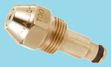
Next we will insert a new siphon feed style nozzle in the block. These nozzle are rated in GPH (Gallons Per Hour). This particular one is a 0.7 GPH Delavan 30609-7. If you clean the old nozzle you will see the flow rating stamped on it. Purchase a siphon feed style nozzle with approximately the same flow rate. These nozzles are the same ones used in commercial waste oil heaters. Notice the little rubber o-ring near the end of the new nozzle. Put a little lubricating oil on it so it will insert without binding and getting ruined. This is what separates the oil and air from mixing prematurely with each other. One of the internal holes has been machined to a specific size for this O-ring.
Delavan waste oil siphon feed nozzle
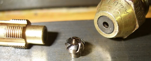
Internals of a Delavan waste oil nozzle
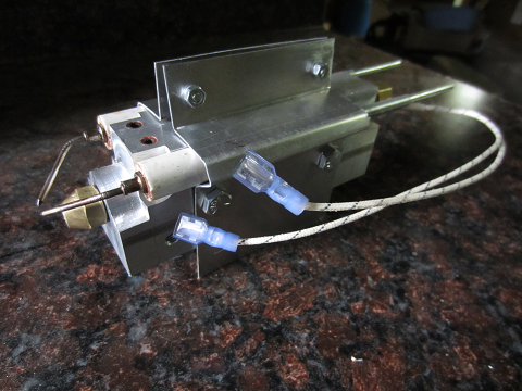
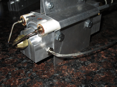
After installing the nozzle, female crimp connectors (for 14/16 guage wire) are crimped on the cartridge heater wires and the electrode clamps installed. These clamps also serve to hold the whole assembly in the flame tube and also to center the nozzle at the center of the flame tube.
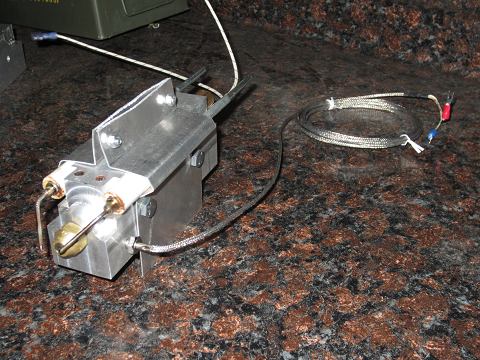
Now the temperature sensor needs to be screwed in. This sensor has soft threads and must not be overtightened. This sensor is what the PID controller will use to know when to turn on/off the cartridge heater to maintain the Aluminum Nozzle Block at a specific temperature.
Next the electrodes need to be adjusted before final tightening of the screws.The tips of the electrodes should be approxiamtely ??? inch apart and ??? inch above the nozzle outlet hole.
I spaced the tips of the electrodes about 3/16 inch apart. (not shown below). Notice the aluminum block cutouts at each end of the ceramic ensulation of the electrodes. If the gap of the electrodes is too large you may get arcing from the nozzle block to the electrodes - typically where the electrode comes out of the ceramic. You will want to look for arcing when you first turn on your system (without any fuel feeeding in). The notches, in the aluminum block, as can be seen in the picture below near the end of the ceramic insulation may need to be deeper depending on your system. Note: In the pictures above and below, the electrodes are not in the final position - they're too forward of the nozzle. The tips, where the arc occurs, will be just above the end of the nozzle when adjusted.
The nozzle assembly is then inserted in the flame tube. Inserting may be difficult and it needs to be a VERY tight fit. If needed trim equal amounts to both the top and bottom of the brackets so the nozzle will stay centered in the flame tube.
The electrode mounting clamps also serve to center the nozzle assembly so that the nozzle ouput hole is right in the center of the flame tube. They can be slightly bent or filed as needed.
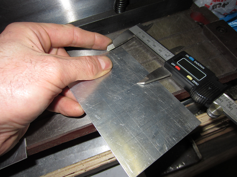
Now we are ready to reinstall the flame tube. Check to be sure the nozzle is centered using calipers or a measuring tape. Now put the flame tube back in place while carefully putting all the wires and copper tubing through the main body side hole where the J tube was previously attached. This will mean careful bending of the copper tubes so that when the flame tube is back in place, the copper tubes will have the same J tube bend - they will be coming out the same angle as the J tube.
4. Creating a New Retention Head
The original retention head does not work well to burn waste oils so it needs replaced with a new design.
A new retention head can be made using a few basic tools. A piece of .031 stainless steel was used. It is about 12 inches long by 2.5 inches wide. Slits are cut every 1/2 inch apart making 24 tabs on one side when done. The slits are 1.25 inches deep. This design was for a flame tube with an inner diameter of 3.87 inches. I used stainless as I figured it would last better, but regular cold rolled sheet steel could also be used and it's easier to bend.
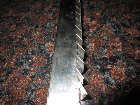
Metal marked with permanent marker before being cut.
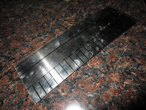
Metal after being cut.
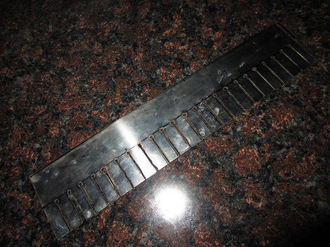
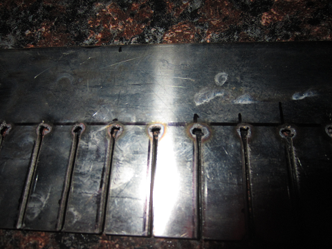
There are small holes at the bottom of the tab cuts becuase this was "hand" cut with a small plasma cutter. The holes even help when bending the tabs due to the tab being slightly narrower where it gets twisted/bent. A bandsaw or hacksaw will work too but it takes a more effort than using a plasma cutter.
Next, each tab should be bent at a 45 degree angle. Pliers or Vise grips work pretty well to do this. Keep all tabs at approximately the same angle. Before clamping in a vise and twisting the tabs, it helps to daw a line (blue line) about 3/4 inch down all the tabs. Us the line as a guide of where to grasp with the pliers for each twist.
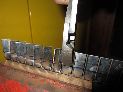
Then the metal needs to be folded at a 90 degree angle at the bottom of the slits as shown and all the tabs checked and adjusted if necessary for uniformity in the twist angle and alignment.
Now the whole thing needs to be bent into a circle and inserted inside the flame tube in place of the old retention head. Note: ignore the misalignment of the electrodes. They will be adjusted later. This is just to show the new rentention head. The 90 degree bend should be aligned with the front edge of the flame tube as shown.
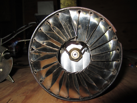
If it is too big for your flame tube, you can straighten it back out a little, trim off a little on one end, bend it back into a circle, and repeat this process if necessary until it fits snugly.
[information on placement relative to nozzle goes here] This design is simple to make and works well.
5. Burner Wiring
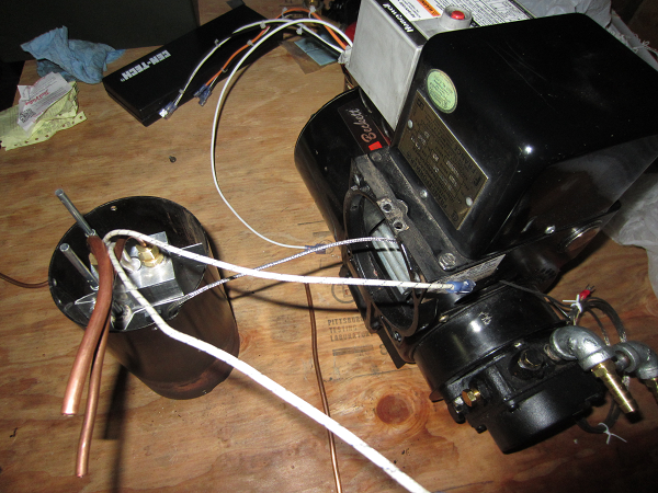
Next, new wiring to/from the burner needs to be made. Remove the 2 screws that hold the Primary Control Unit in place and genlty lay it over as shown.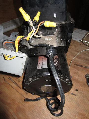
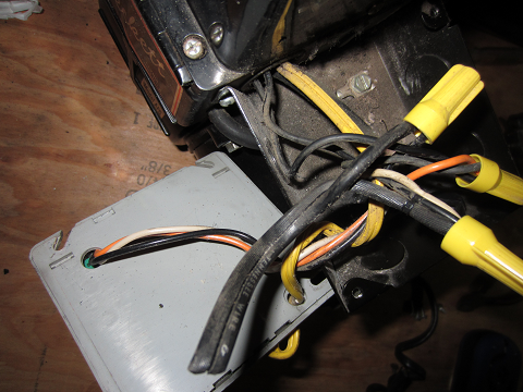
First, cut/remove the 110VAC (USA standard) wires coming into the box under the Primary Control Unit. In the following picture the 110VAC wires are both black and physical joined side by side. Note that one goes to a bundle containing a white wire and one to a bundle containing just black wires. Some burners may actually have power wires coming in that are black and white and not both black.
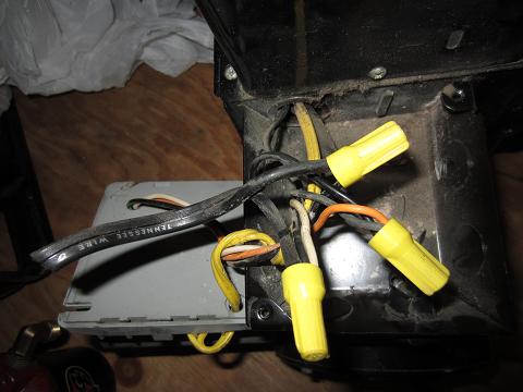
There are 3 wires (white, black, orange) that go through a hole in the bottom of the PCU. These wires also go to wire nuts as shown. Notice the yellow wires go to the inside of the blower and they connect to the cad cell (flame detector). Do not bother the yellow wires.
Three new wire bundles will be made. Locate which wire nut the PCU's white wire goes to and untwist the wire nut and remove any of the 110VAC power wires that were disconnected/cut above. Then strip both ends of a 4 inch piece of white wire. Connect one end of the 4 inch piece to the group of wires that you just took the wire nut off of. Also connect a single long (2ft) wire to this same connection. The other end of the 4 inch white wire then connects to two new long (2 ft) pieces of 14 guage white wire (multi stranded type) and a new the wire nut (center yellow one) is added. In this example, a larger Red wire nut was used becuase of the number of wires in that connection group. Similarly, two new long (2ft) black wires need to be added to the "hot" wire nut connection. For the orange wire, only one new long (2ft) orange wire is added. Small Zip-ties were used to keep the wires together neatly and help prevent them from getting pulled apart.
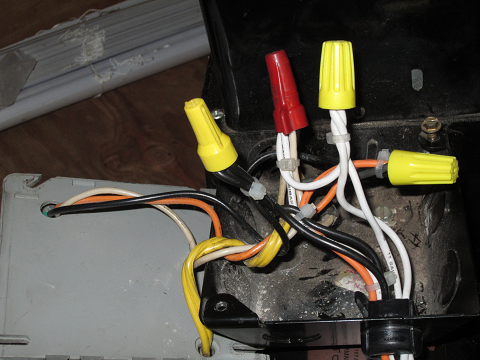
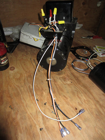
Now there are three wire bundles all of which use 14 guage wire: 1.) a single white wire, 2.) an orange/black/white bundle and 3.) a white/black bundle. The bundle with the orange wire will connect to the Circuit Panel (see Circuit Panel webpage) wire bundle. The single white wire will connect to one of the cartridge heater wire leads. The other wire bundle with just a white/black pair are used to connect to the furnace power which supplies power to the burner and all electronics. At the end of the wire bundles, 14/16 guage female crimp connectors have been added on all the wires except the single white wire which has a male crimp connector to match the female connectors that are placed on the cartridge heater leads. Note: the actual length of the white/black wire bundle needs to be long enought to connect to the main furnace power the burner was previously connected to. The length of the white/black/orange bundle needs to be long enough the connect to the matching bundle that comes from the Circuit Panel. Similarly the single white wire needs to be long enough to reach the cartridge heater leads. Keep this in mind when building the Circuit Panel wire bundles. You may want to leave off the crimp connectors until it is time to connect them and thus you can shorten wires that may be too long.
Now the Primary Control Unit can be put back and screwed down.
6. Flame Tube Reassembly
First, the old 3/16" high oil pressure line needs to be removed from the pump.
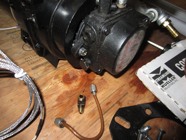
Once removed, buy & install a brass plug that fits the hole to keep oil from coming out the pump hole. Usually its a 1/8" NPT brass plug. Now the flame tube assembly will be installed
Before installing, a length of 3/16" O.D. copper tubing will need to be cut and installed on the oil input port as shown. Note the double wrenches being used to keep the fitting from being overtightened while installing this tube. The block is made of aluminum so some caution should be taken to avoid stripping the aluminum threads.
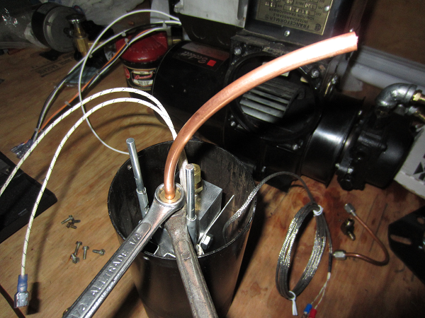
Similarly, a length of 1/4" copper tubing for the compressed air input was made and installed. The lengths of these tubes depends on the length of the particular flame tube being used. See more pictures below to get an idea of how long they may need to be.
The tubes will need to be bent so that once installed they come out of the side of the case correctly. Now carefully begin installing the assembly. Be careful to not let the wires for the cartridge heater and temperature sensor get pulled or damaged while installing.
...and install the 4 screws that hold the flame tube to the burner case.
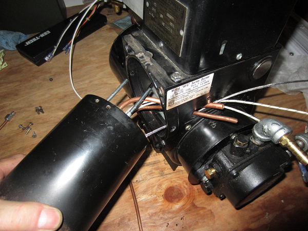
Once assembled, the copper tube will come out perpendicular to the case as shown below.

Then brass fittings that allow easier installation/removal can be added. I this example a 3/16"o.d. compression by 3/16" O.D. compression fitting was added to the oil feed line and a 1/4" O.D. compression by 1/4" Male NPT fitting plus a 1/4" NPT Female NPT quick connect air fitting added to thecompressed air supply line.
It may be easier during installation to flip open the high voltage transformer while doing the flame tube installation.
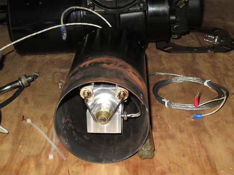
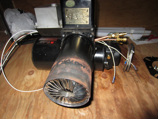
Once reassembled it should be similar to the one shown below.
7. Adjustment of the Nozzle Block
Next, make sure the nozzle block is somewhat aligned vertically. In this example the block is rotated a bit and needs to be readjusted.
8. Retention Head Adjustment/Placement
In placing the retention head in the tube, place the "fingers" as close to the nozzle as possible without causing arcing from the electrodes to the retention head. Allow an extra 1/8 inch or so of spacing just to be sure it won't arc.
9. Modified Burner Installation
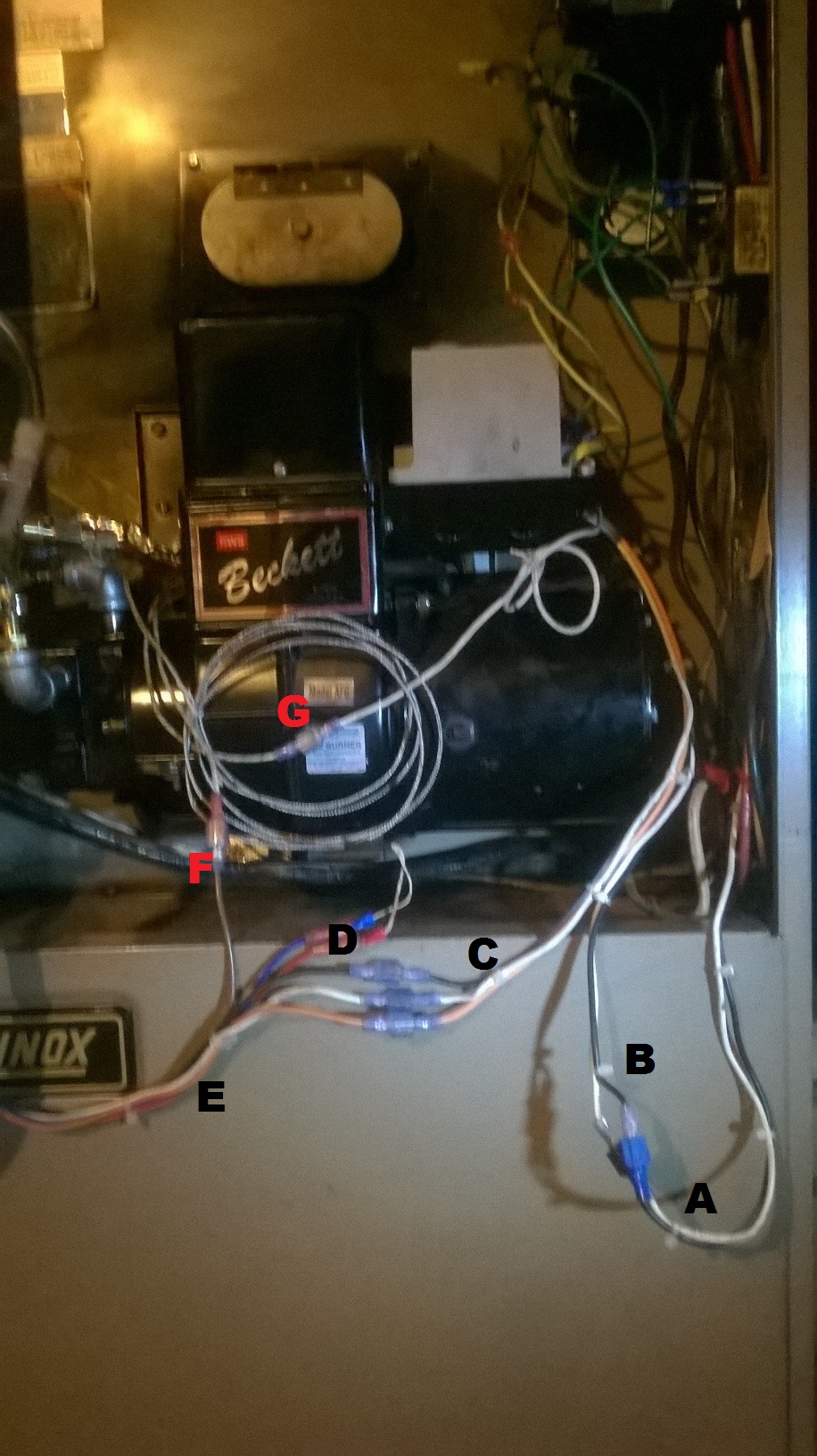
A. These are 120VAC power lines from power lines coming into the furnace and to the burner.
B. New power wires (black & white bundle) that go into the Control Unit
C. New cable (black, white, orange) that comes out of the Control Unit and connects to the same colored wires in the wire bundle (E) from the Circuit Panel.
D. Red & Black wires from the Circuit Panel wire bundle which connect to the temperature sensor wires going to the nozzle block temp. sensor.
E. New Circuit Panel wire bundle of which the brown wire attaches to one of the cartridge heater wires (F). The other cartridge heater wire connects to the single white wire bundle from the Control Unit ( G)
In this particular furnace you can see two yellow wires and green wires that now have spade connectors making it easy to remove this whole assembly when needed. Any external connections the Control Unit not discussed in this website will still need to be connected as they originally were, such as the yellow (to furnace temp. limit unit) and green (thermostat control) wires this furnace unit had.
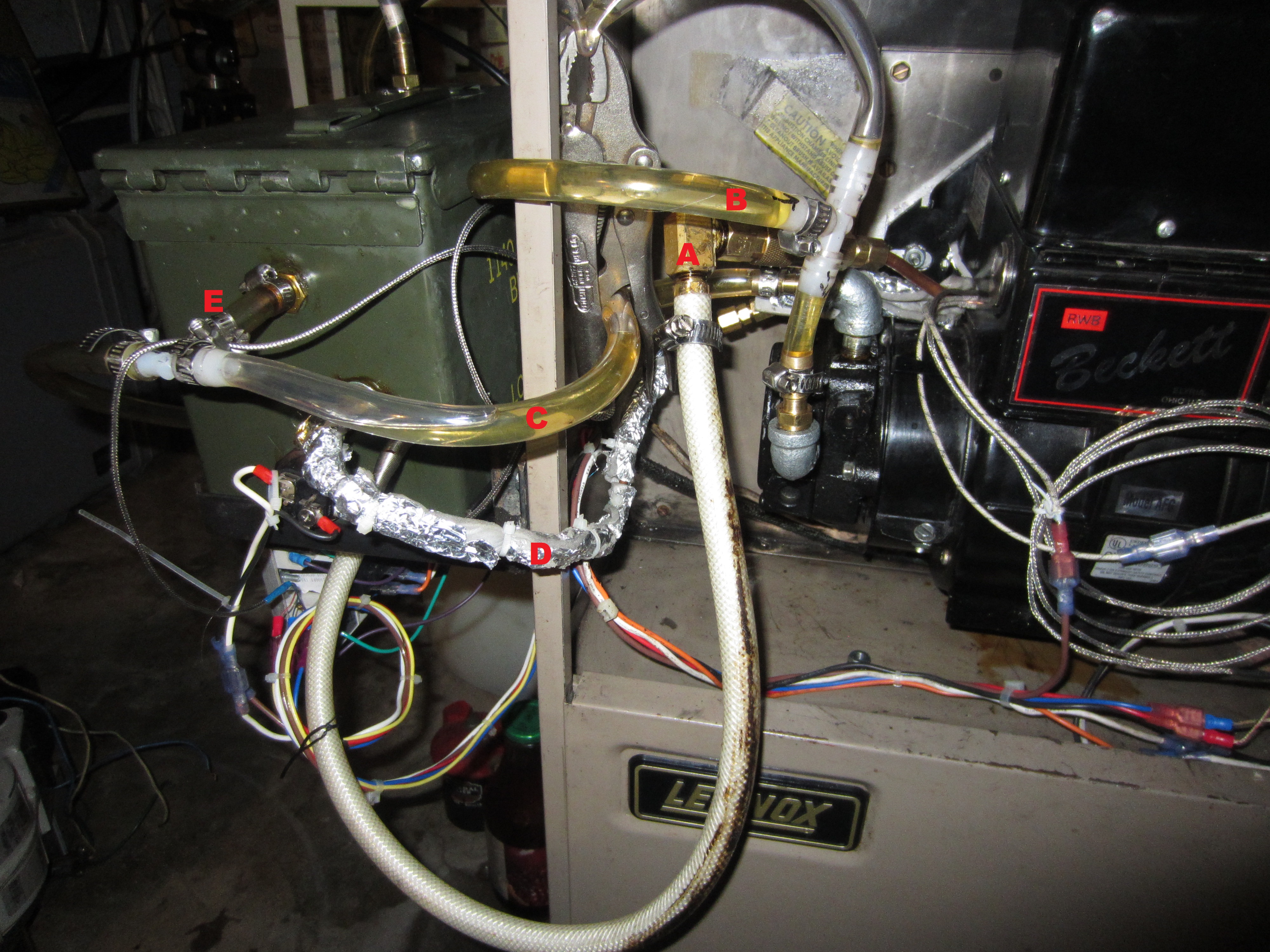
A. Quick connect/disconnect fitting from air hose on Circuit Panel to fitting that goes to the nozzle block.
B. Waste oil from external tank to the oil pump input on the burner unit
C. Waste oil from the oil pump output back to the external tank. Note the T connection (E) into the Preheat/Constant Level tank (green ammo box modified)
D. Insulated hot oil feed line from Preheat/Constant Level tank to nozzle block
I used clear 3/8 inch PVC tubing so I could see the oil flow and whether I was getting air into the lines during normal operation. Initially I did get some air from a couple leaking connections, so the clear tubing works great. You just can't let it get kinked or it doesn't do well. You will also notice above I added a T connection near the letter B. This was because initially I had air in the line and the pump didn't like it until I bled out the air. You can also see the ViseGrips clamping this bleed tube shut until I make a more permanent solution. Once the air was bled out this pump worked fine. Its a different pump than on my other burner units which dont seem to mind the air in the line.
10. Bringup & Troubleshooting
Bringup
1. Make all Burner physical and wiring modifications, build the Circuit Panel and setup a waste oil tank.
2. Turn off your furnace thermostat so the furnace wont run.
3. Mount the modified burner and tighten to furnace.
4. Mount the Preheat/Constant Level tank.
5. Mount the Circuit Panel.
6. Connect all wires as shown in section 9. pictures above. Reconnect any others that were not a part of this modification but were connected before the burner was taken out of the furnace and modified. See the discussion in section 9 above about the yellow (furnace temp. limit) and green (thermostat control) wires.
7. Connect Preheat/Constant Level tank temperature sensor and heating element wires as shown in the last two pictures Circuit Panel webpage.
8. Connect the hot oil feed line to the nozzle block.
9. Connect all oil pump feed & return lines.
10. Connect the compressed air line.
11. PID setup.
Make sure that one wire to the Preheat Tank element and one wire to the cartridge heating element are disconnected and not touching anything BEFORE programming the PIDs.12. Now program the PIDs according to the PID Setup webpage. Set the Preheat Tank PID for 140F.
Jan. 4, 2015: I have been running this burner for 130 hrs (on the hour meter)of WVO and pulled it out. It seemed to have a lot of build up on the retention head tabs and end of nozzle so I removed every other tab (only 12 now) and its seemes to be burning better. Will post update here after I run it awhile. I also reduced my nozzle block temp down to 250F from 280F. May have caused more build up at 280F, we'll see... If anyone has any improvements to the retention head design, please let me know.
13. Reconnect the wires disconnected in step 11.
14. Mount and fill the Preheat/Constant Level tank with filtered waste oil so that the waste oil is slightly above the hot oil outlet line.
15. Turn on all switches on the Circuit Panel.
The temperatures on the PIDs should rise and overshoot the desired setting by up to 20 degrees before slowly settling back down toward the target temperatures.
16. Once temperatures are close to the target temps. turn on the burner by turning on your furnace thermostat.
Testing pieces of the system
Before performing each of the tests in this section, make sure all electrical, oil & air supply line connections are disconnected. Also turn off all switches on the Circuit Panel.
These tests allow you to test parts of the system to make sure individual parts are functioning correctly. Remember, several of the wires are 120VAC lines so be careful not to touch the bare wires or connectors during the tests. I recommend having a couple of short (under 2 ft and 14gauge or better wire) alligator jumper style wires for making some of the connections.A. Preheat tank oil heat test.
This test will check to see that you have the PID working that controls the Preheat Tank oil temperature. Make sure the tank is filled with filtered waste oil to just above the hot oil outlet. Connect the white & black wires of the white/black/orange/red/blue/brown bundle of the Circuit panel to the furnace power supply lines. Turn on the Circuit Panel main power switch and small toggle switch to supply power to the PID. When you first turn the PID on, IF the temperature probe wires are connected correctly and the PID is programmed correctly (140F) you should see the current temperature of the probe in red on the display and the desired temperature (140F) in green. The temperature should begin to climb toward the 140F. Normally it may go 20 degrees or more past 140F before coming back down. It's important here to carefully watch that it doesn't go to high and just keep climbing (wires may be connected wrong) and that the set temperature is correct.B. Air supply test.
This test should cause the air supply solenoid to open and compressed air to come out of the nozzle on the nozzle block. For this test make sure no oil is supplied to the nozzle block. Connect up the compressed air supply to the air regulator. Connect the white wire (nuetral/gnd) of furnace's power lines to the white wire in the white/black/orange/red/blue/brown bundle of the Circuit Panel. You may have to use a jumper wire if your connectors are both male or both female. Then momentarily connect the black wire from the white/black bundle from the furnace power linesto the orange wire of the white/black/orange/red/blue/brown bundle of the Circuit panel. Basically we are directly suppling 120VAC to the orange wire in the Circuit Panel to make the Air solenoid open up. You should now be getting air out of the nozzle. Undo all connections after test. If you wish to modify this test to see if waste oil is siphoned and sprays out in a mist then be sure to do the test outside in a well ventilated area where oil spraying all over will not bother anything. The oil will need to be heated and I suggest using vege oil.C. ............more tests coming soon....
Troubleshooting
A. Burner doesn't ignite.
1. No oil getting into the nozzle. Check to see that the small copper tubing is not clogged. Also check to see that the float is working properly and that the oil level in the Preheat/Constant Level tank is above the hot oil outlet hole. THis may be caused by the float is not adjusted properly or having a problem.
B. Burner pulses and goes out.
I've seen this happen when the float doesn't work properly. Sometimes the oil in the Preheat/Constant Level tank is above the hot oil outlet and sometimes its just right at the outlet causing air to get sucked in and the flame to pulse.
C. Burner fires up but then stops suddenly.
Most likely the CAD cell thats under the high voltage transformer is not getting enough light from the flame and needs to be repositioned. I had to move one of mine over on the side of the flame tube.
D. Oil level in Preheat/Constant Level tank doesn't stay constant or works erracticly.
This may be caused by a sticking valve or it can be caused by not having a slight pressure of oil in the line. On my setup the return tank is lower than the T at the Preheat tank and oil just tends to flow from the oil pump output, through the T, and back to the tank without going very well into the float valve. Since I had a 1/4 turn ball valve I turned the valve about 45 degrees. It was enough to cause a slight back pressure at the T and float valve but not enough that it stopped oil from flowing into the tank or from flowing out the overflow tube. This problem may also be caused by air in the oil pump input line causing it not to pump out oil to the Preheat tank's float valve input. Clear PVC tubing is great to see what is happening especially if your system is just being brought up for the first time.
E. No arc at electrodes.
You may be getting arcing from the electrodes to the retention head or to the nozzle block.
F. No oil flow through burner oil pump.
Look for air in the line, or a closed valve from your tank, kinked or plugged lines.
G. Oil comes out the Preheat/Constant Level tank vent tube!
H. Red reset switch pops up on the Control Unit.
I. Flame in furnace is small and can't make it larger.
J. build up on retention head tabs and end of nozzle.
...
Anyone with other interesting issues please contact me.
11. Misc Information...
PID Controllers & Solid State Relay Electronics
The PIDs will be discussed in more detail on other web pages of this project.
For a detailed explanation of what a PID controller is and does, please visit http://en.wikipedia.org/wiki/PID_controller. For this project a PID controller will be used in the burner conversion as well as the preheat/constant level tank design. Basically they will be used to control the temperature of each. In order to do this, three other devices will be needed - 1) 25 Amp Solid State Relay, 2) heating element, and 3) a temperature sensor. For both the burner conversion and the constant level/preheat tank, the same 25 Amp SSR will be used, but the heating elements and temperature sensors will be different. Please see the PID Setup webpage to learn more about how to setup the PID controllers.
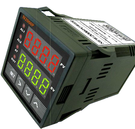
PID controller
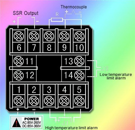
Typical connections on the back of the PID controller
SSR (Solid State Relay)
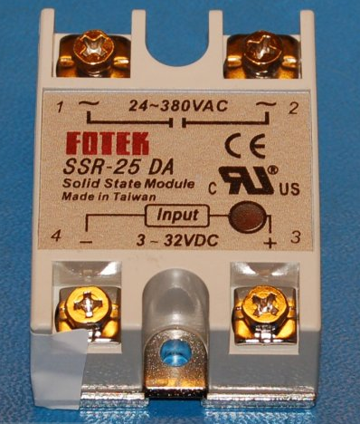
Notice that this SSR has a 3-32V DC input and can handle a 24-380VAC load of 25Amps. These can be obtained on EBay for around $5. Also notice in the PID connections above that the PID controller has an SSR connection. It has an SSR voltage within the range of Input of the SSR so they are compatible. The output side of the SSR is used to control the heating element (such as a 120VAC 750W cartridge heater). Another nice feature of this SSR is that it has a red LED (dark red circle near terminal #3) that lights up whenever there is an input voltage. During operation, you can see how often and how long it is on - supplying power to the heating element.
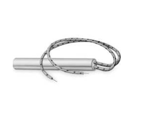
Cartridge Heater - 120VAC, 750W, 4 inch long, 1/2 inch diameter
Temperature Probe - this is a "K type thermocouple " that comes with the PID that I purchase, otherwise get them for under $3 on EBay
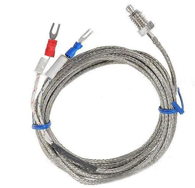
The threads on these are soft and care must be taken not to overtighten when screwing this onto the side of the Aluminum Nozzle Block. Notice the red/blue connectors. These will have to be connected correctly to the PID controller or the temperature will read incorrectly. The temp reading may go down instead of up when the sensing probe is heated if these are incorrectly connected.
Compressed Air Supply
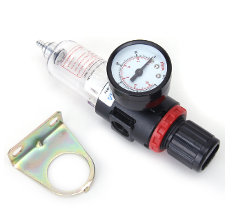
In order for the siphon feed nozzle to work, a compressed air source is needed. Right now I use an external air compressor, but someday would like to make a small integral one that's part of this modification - possibly an old refrigerator compressor which is small and quiet. The amount of compressed air need may be in the range of about 1-2 CFM (Cubic Feet per Minute) at about 6-10PSI. I currently run around 7 PSI on my unit. The amount you will need for your system will vary due to several factors, but we'll talk about that later. For now, you will need an air pressure regulator capable of handling the air pressure range of your compressor AND capable of being adjusted in the 5 - 10 PSI range. I replaced the gauge on my regulator with one that goes from 0 - 15PSI so I could fine tune the pressure better. You will also need a 120 VAC electric solenoid valve capable of turning the air supply to the nozzle block on or off. This is shown in the Circuit Panel information.
Air Pressure Regulator
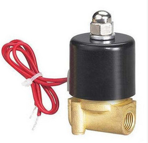
1/4 inch NPT, 120VAC, Electric Solenoid Valve
History - First Prototype:
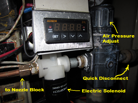
The following picture is from my first prototype. The air supply is connected to the air pressure regulator with a quick disconnect fitting. Since the burner will need to be serviced at times, it is best that all connections from the burner to other components be able to be disconnected/reconnected easily. The regulator is then connected to the solenoid valve which is then connected via the 1/4 inch copper tube to the aluminum nozzle block inside the burner we previously assembled back together. Here we see the burner PID controller mounted at the burner. In the latest design this will be on a panel with the PID controller for the Preheat Tank as well as the air pressure regulator and solenoid.
Note that the motor is only on when the Primary Control Unit allows it. This is why there's an orange wire that comes out of the PCU. However, the PID controller needs to be on whenever power is supplied to the furnace, thus we need the white/black power wires supplied through the metal flexible conduit as seen earlier. I like to put a fuse and a switch in series with the black "hot" wire before it connects to the PID so I can shutoff the PID if I want to burn regular home heating oil (diesel) as we dont want to preheat the diesel. It also allows me a way to shut it off if a problem should develop with the temperature sensor or something.
In the picture above, notice the PID controller is a single line controller. This was before I found a better price on the 2 line display units. Here it's mounted in a small metal box with the solenoid valve mounted underneath. I mounted the switch to turn on/off the PID on the side of the metal box under the burner's Primary Control Unit. The SSR (solid state relay) is mounted above the PID.