How does a home heating oil furnace basically work?
This is important to know because you will be modifying it to work a bit differently and you will also need to be able to service this conversion at some point in the future. A home heating oil furnace burns heating oil which is basically #2 diesel fuel.
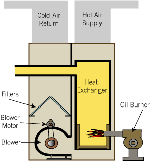

Oil is delivered to the home and pumped into a storage tank. A common tank size is 275 gallons but some homes have much larger tanks. Oil from the storage tank is drawn into the burner. The burner atomizes the oil (turns it into a mist of tiny oil droplets), mixes it with air and ignites it with a spark. The resulting flame shoots out of the flame tube/blast tube and into the burner chamber. Combustion gasses move through the heat exchanger where heat is transferred to the household air stream. The combustion gasses then make their way up the flue and out of the house. The blower pulls in air through the Cold Air Return, blows it over the sealed Heat Exchanger and then out (Hot Air Supply) - typically in a home this would be through the duct work to the rooms through the floor vents.
Here's a typical furnace with the panel removed so you can see the burner and other parts. In this case the burner is made by Beckett which is the brand I like to modify.
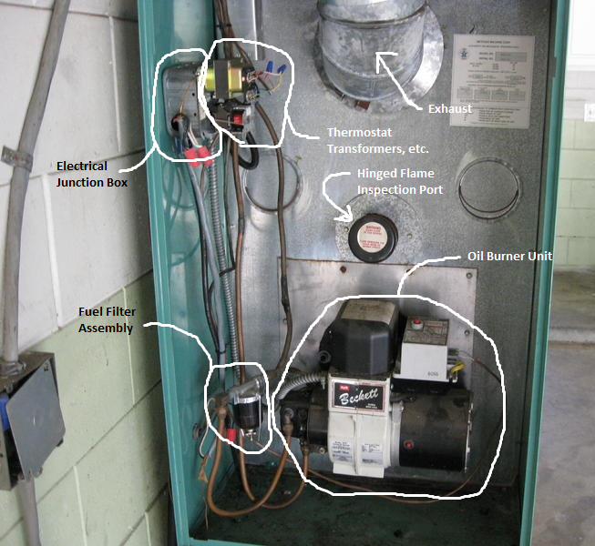
The Beckett burner consists of a motor (large round black area to bottom right of Beckett label), an oil pump (smaller black area with two copper lines attached to the left of the Beckett label), a high voltage transformer/igniter which is used to create the fuel ignition spark (block box above the Beckett label) and a primary control unit with a red rest button on it (to the top right of the Beckett label). Inside the white colored portion of the OIl Burner Unit shown above is a small squirrel cage type blower fan that blows air through the flame tube and into the combustion chamber.
Other items in the above picture:
a. flame inspection port - this is used to check the flame inside the combustion unit. In this picture it is the round black/white object just above the burner. It is hinged so that the owner/service person may inspect the internal flame when needed.
b. fuel filter - notice that there are two copper lines connected to the oil pump. One is for fuel feed from the oil tank to the oil pump and the other is return for unused fuel back to the oil tank. Notice the black/aluminum object just to the left of the burner with the copper lines attached - this is the fuel filter.
c. exhaust - this is partially seen at the top middle of the picture and is typically around 6 - 8 inch diameter galvanized pipe
d. power/transformers - mounted up high inside the furnace on the green sheet metal. Power for the furnace may be connected here as well as various transformers that get used for things like thermostats.
Please refer to http://visual.merriam-webster.com/house/heating/forced-hot-water-system/oil-burner.php to see the parts of a typical burner
Oil Pump
The oil pump on the burner takes part of the incoming oil and pressurizes it to around 100psi (high pressure) to send to the spray nozzle so that the fuel will atomized into very tiny droplets which can readily be burned using an electric arc or spark.
Motor
The motor is used to run the oil pump and the air blower.
High Voltage Transformer/Igniter
Whenever the motor is on, power is also supplied to this igniter which creates a very high voltage in order to produce an arc between the two nozzle electrodes to ignite the atomized fuel spray coming out of the nozzle. A high voltage arc is being created between the electrodes and one must be very careful not to have power connected to the burner when working on the burner or else you may get a bad shock. Although this is typically called an Igniter, it's basically a high voltage transformer - similar to an "ignition coil" in an automobile.
Primary Control Unit
Inside the blower area a CAD cell is mounted facing the flame at the end of the blower tube. This CAD cell is used to detect the flame. Once power is applied to the motor and transformer/igniter, the Primary Control Unit checks to see that a flame is being created. If there's no flame after a certain amount of time then the Primary Control Unit shuts down the burner unit until someone resets it by physically pushing the red reset button on top of the Primary Control Unit. Typically, a wait of a couple minutes or so is needed before the control unit will allow someone to reset the system. This is a safety feature. Should a flame never be generated then unburned diesel fuel would keep spraying into the combustion chamber. Imagine this happened for a long time and then all of a sudden it ignites... :( ... a very sad day for your home, cabin or building...should you survive.
This is a brief overview of the furnace but please familiarize yourself with it and look for other websites showing how they work to get an even better idea of how they work.